Maze Solving Robot

(AlphaBot2)


Autonomous Maze Solving Robot can perform tasks intelligently depending on itself, without any human assistance. Maze Solving Robot is one of the most popular autonomous robots. It is a small self-reliant robot that can solve a maze from a known starting position to the center area of the maze in the shortest possible time. It can make multiple runs in a maze, first it creates a map of the maze layout and store it in its memory, then run through a shortest path.


Specifications:


3.1. How is it built?

AlphaBot2 is composed of two circular frames, doubling as printed circuit and chassis for the robot. The bottom one has two motor reducers with high precision, low noise metal cogs, commanded by a double H-bridge driver with high-efficiency based on the TB6612FNG, the wheels are 42 x 19 mm, made out of high grip rubber. We still have five ITR20001/T infrared reflection linear sensors, two ST188 front infrared obstacle sensors, and an HC-SR04 ultrasound sensor. The hardware is finished off by four Neopixel LEDs, independently and serially controlled.

Anyways, these are SMD latest generation components (except for the ultrasound sensor) of the highest quality. The power is provided by two, 3.7 V 14500 lithium polymer batteries, with 800 mAh capacity, providing long working life with reduced weight and encumbrance. There is no internal recharge in the circuit but charging circuit, therefore, once the batteries are dead, the bot must be plugged in.

The upper frame has a housing for the Arduino board (not included in the kit), 0.66 inches, 128×64 yellow/blue bicolour OLED display, a TLC1543 AD converter, a joystick, a buzzer and an expansion module for I/O is based on the integrated PCF8574. The latter component is used to optimize the use of the I/O lines of the Arduino board, which are not enough to handle the many onboard peripherals.

On the upper part, there are also all the classic connectors of an Arduino board and an XBee-compatible connector. A connector called Control JMP is also available, allowing to redefine the features of the Arduino pin in relation to the hardware on the board. For all the details on the functionalities of the Arduino pin, please look at Table 1.

Table 1
Arduino Pin Function
0 RX/ RX XBEE
1 TX/ TX XBEE
2 ECHO ultrasound sensor
3 TRIG ultrasound sensor
4 IR infrared remote control sensor
5 PWMB Right Motor Speed pin (ENB)
6 PWMA Left Motor Speed pin (ENA)
7 RGB serial command for RGB LEDS
8 D/C for OLED display
9 REST for OLED display
10 CS for ADC module
11 DOUT for ADC module
12 ADDR for ADC module
13 CLK for ADC module
A0 AIN2 Motor-L forward (IN2)
A1 AIN1 Motor-L backward (IN1)
A2 BIN1 Motor-R forward (IN3)
A3 BIN2 Motor-R backward (IN4)
A4 SDA for I/O expansion module and OLED display
A5 SCL for I/O expansion module and OLED display


The ADC module is used to measure the batteries voltage and the light values of the five line sensors. The expansion module connected to the I²C port is used to read the status of the joystick keys and the two front distance sensors; these have a digital output, therefore they allow to determine the presence of an object in front of the robot but they do not provide information on the distance.


AlphaBot2 Base


  1. AlphaBot2 control interface : for connecting sorts of controller adapter board
  2. Ultrasonic module interface
  3. Obstacle avoiding indicators
  4. Omni-direction wheel
  5. ST188 :reflective infrared photoelectric sensor, for obstacle avoiding
  6. ITR20001/T : reflective infrared photoelectric sensor, for line tracking
  7. Potentiometer for adjusting obstacle avoiding range
  8. TB6612FNG dual H-bridge motor driver
  9. LM393 voltage comparator
  10. N20 micro gear motor reduction rate 1:30, 6V/600 RPM
  11. Rubber wheels diameter 42mm, width 19mm
  12. Power switch
  13. Battery holder: supports 14500 batteries
  14. WS2812B : true color RGB LEDs
  15. Power indicator

AlphaBot2-Upper Part


  1. AlphaBot2 control interface : for connecting AlphaBot2-Base
  2. Arduino expansion header : for connecting Arduino shields
  3. Arduino interface : for connecting Arduino compatible controller
  4. Xbee connector: for connecting dual-mode Bluetooth module, remotely control the robot via Bluetooth
  5. IR receiver
  6. PC8574 : I/O expander, SPI interface
  7. Arduino peripheral jumpers
  8. TLC1543 : 10-bit AD acquisition chip
  9. Buzzer
  10. 0.96 inch OLED SSD1306 driver, 128x64 resolution
  11. Joystick

AlphaBot2-Assembling


3.2. Arduino


The heart of this project is Arduino. All program of this project is stored in its microprocessor. Arduino is an open source hardware development board. Arduino hardware consists of an open hardware design with an Atmel AVR processor. Arduino programming language is used to program the processor.

There are many types of Arduino board available in the market. But, in this project Arduino UNO has been used. Figure 3.4 shows the Arduino UNO board and Software IDE.


Arduino UNO is based on the ATmega328P microprocessor. It has 14 input/output pins. 6 digital pin can be used as PWM outputs. It has 6 analog input pins. It has a 16 MHz quartz crystal. It contains USB connection port, dc power port. The microcontroller is programmed via Arduino Software (IDE). See the pin mapping of Arduino UNO below.


3.3.Tracker Sensor

Detect on Black and White Surface

Tracker sensor has five analog outputs, and the outputted data are affected by the distance and the color of the detected object. The detected object with higher infrared reflectance (in white) will make larger output value, and the one with lower infrared reflectance (in black) will make smaller output value. When the sensor is getting close to a black line, the output value will come to smaller and smaller. So it is easy to get the distance from the black line by checking the analog output (The closer distance between the sensor and the black line, the smaller output value you will get).


3.4.TB6612FNG Dual H-bridge Motor Driver


Dual H-bridge Motor Driver

The TB6612FNG is an easy and affordable way to control motors. The TB6612FNG is capable of driving two motors at up to 1.2A of constant current. Inside the IC, you'll find two standard H-bridges on a chip allowing you to not only control the direction and speed of your motors but also stop and brake. This guide will cover in detail how to use the TB6612FNG breakout board. The library for this guide will also work on the RedBot Mainboard as well since it uses the same motor driver chip.Its specifications are as follows:


3.5. N20 micro gear motor


This gearmotor is a miniature high-power, 6 V brushed DC motor with a 150.58:1 metal gearbox. It has a cross section of 10 × 12 mm, and the D-shaped gearbox output shaft is 9 mm long and 3 mm in diameter.


3.6.OLED


0.96 inch OLED, 128x64 resolution

This OLED display module is small, only 0.96” diagonal, it is made of 128x64 individual yellow and blue OLED pixels, each one is turn on or off by the controller chip. It works without backlight, that is, in a dark environment OLED display is higher compared to that of LCD display you will like the miniature for its crispness.The Driver chip of this OLED is SSD1306, which is compatible with I2C communication. So this module can be controlled by I2C. That is, except the VCC and GND, 2 wires would be needed when using 4-wires I2C mode. There is also a simple switch-cap charge pump that turns 5v into a low voltage drive for the OLEDs, making this module the easiest ways to get an OLED into our project.


Features:

3.7.Batteries


14500 batteries

We are using two 14500 batteries to power AlphaBot2. Each battery relates to other in series connection. As a battery can supply 3.7V, two batteries in series become 7.4V.


4.1. Wall Following Algorithm

The most common algorithm for maze solving robot is Wall following algorithm. The robot will take its direction by following either left or right wall. This algorithm also called, left hand-right hand rules. Whenever the robot reaches a junction, it will sense for the opening walls and select it direction giving the priority to the selected wall. By taking the walls as guide, this strategy is capable to make the robot reaches the finish point of the maze without actually solving it. But, this algorithm is not efficient method to solve a maze. Cause, the wall follower algorithm will fail to solve some maze construction, such as a maze with a closed loop region.

The instructions used in the algorithm for both left and right wall are given below.

Right wall following routine Left wall following routine
if there is no wall at right, if there is no wall at left,
turn right turn left
else else
if there is no wall at straight, if there is no wall at straight,
keep straight keep straight
else else
if there is no wall at left, if there is no wall at right,
turn left turn right
else else
turn around turn around

4.2. Bellman-Ford Algorithm

Like Dijkstra's algorithm, Bellman–Ford proceeds by relaxation, in which approximations to the correct distance are replaced by better ones until they eventually reach the solution. In both algorithms, the approximate distance to each vertex is always an overestimate of the true distance, and is replaced by the minimum of its old value and the length of a newly found path. However, Dijkstra's algorithm uses a priority queue to greedily select the closest vertex that has not yet been processed, and performs this relaxation process on all of its outgoing edges.

In each of these repetitions, the number of vertices with correctly calculated distances grows, from which it follows that eventually all vertices will have their correct distances. This method allows the Bellman–Ford algorithm to be applied to a wider class of inputs than Dijkstra.

Bellman-Ford Algorithm


5.1.Operation Flowchart

Fig-5.1.:Operation Flowchart


5.2.Block Diagram


Fig-5.2.:Block Diagram


5.3. Software Development

The maze running software have been developed using two known maze solving algorithms.

Before software preparing for running and finding the shortest way in maze using these two algorithms, first explain the “Lighting and Display process for show for the car of analyzing in the maze. In this, we use Header files of -

			#include <Adafruit_NeoPixel.h>
			#include <Adafruit_GFX.h>
			#include <Adafruit_SSD1306.h>
		

To show lighting with 4 Neo Pixel under the base bot developed this 4 neons to change of customize colours change of millions of color is based on only RGB channel.

For Displaying on OLED board, we use the above under 2 library files.On board, first display "TU(Hmawbi)", "Maze Solver", "Press to calibrate" with white color before robot running. If we push the switch, this calibrate done and Display "Calibration Done !!!", "AlhpaBot2" "Go!" and staring to running.

Bot runs first along the routine in the maze as it wish without unknown where the shortest way is and whenever it reaches the dead end it turn to left and more 90 degree(U turn) and delete the routine that way to dead end from the path way. After this bot is at end, we again run the bot from where we started first and in this time the bot is running the shortest way to the goal. For this we use #include"TRSensors.h" library. To solve the maze, we have Left hand rule.


Looking the picture, we can realize that the possible actions at intersections are

  1. At a "Cross" :
    • Go to Left, or
    • Go to Right, or
    • Go Straight

  2. At a "T" :
    • Go to Left, or
    • Go to Right

  3. At a "Right Only" :
    • Go to Right

  4. At a "Left Only" :
    • Go to Left

  5. At a "Straight or Left" :
    • Go to Left, or
    • Go Straight

  6. At a "Straight or Right" :
    • Go to Right, or
    • Go Straight

  7. At a "Dead End" :
    • Go back ("U turn")

  8. At a "End of Maze" :
    • Stop


However, applying the "Left-Hand Rule", the actions will be reduced to one option each:

While running the bot along the path it need to normalize of go. For this we use Normalization process and weighted average and PID control.


5.3.1. Normalization process

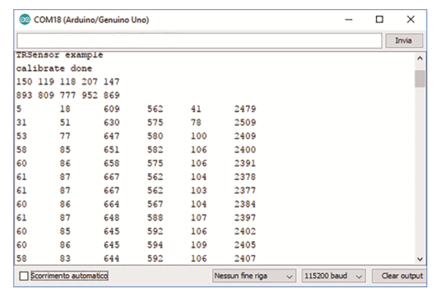
Different sensors may output different results for the same color and distance. Furthermore, environment can affect the range of analog output. For example, if we apply 10AD for sampling, we may get the output range from 0 to 1023 theoretically.

However, what we get actually will be the Min output value higher than 0 and the Max output value lower than 1023. Normalization process is important and necessary for reducing the affecting factors from different sensors and different environments. Normalization process is a kind of linear transformation by transforming the range of Min~Max to the range of 0~1 with the following formulas.

y = (x-Min)/(Max-Min)

In which, x is the original output value from sensor, y is the transformed value, and Max and Min are the maximum output value and the minimum output value, respectively.

y = ((x-Min) * 1000)/(Max-Min)

After transformed, the output value will be in the range of 0~1000, in which 1000 means the sensor is far away from the black line, and 0 means the sensor is above the black line.

The program will sample the values from the sensors for many times to get the proper value of Min and Max. In order to get the precise Min and Max, the car should be always running in course of sampling.

5.3.2. Weighted average

Using normalization process to deal with five sets of output data, we will get five sets of data about the distances between the sensors and the black line. Then, we should use weighted average to transform these data into a value to determine center line of the route with the following formula:

y = ((0 * value0) + (1000 * value1) + (2000 * value2) + (3000 * value3) + (4000 * value4)) /
(value0 + value1 + value2 + value3 + value4)

In which, 0, 1000, 2000, 3000, 4000 are the weights for the five detectors, respectively, from left to right. And value0~value4 are the data with normalization process.

Now, we can get the data in the range of 0~4000, which can tell you the position of the black line. For example, 2000 means the black line is in the middle of the module, 0 means the black line is on the leftmost side of the module, and 4000 means the black line is on the rightmost side of the module.

For more precise detection, we have some requirements on the height of the module and the width of the black line. The width of the black line should be equal to or less than the distance of two sensors (16mm). The proper height of the module is that when the black line is in the middle of two sensors, both sensors can detect the black line.

5.3.3. PID Control

From Part 2, we can get the position of the black line. You should make sure the black line is always under the car, so that the car can run along the black line. So, the output value after weight average process should be kept at 2000. Here, we employ positional PID control to make the car run smoothly. About the PID algorithm, you can easy get a lot of information via Internet. In here, we only have a brief description on it.

PID control can feedback and regulate the error with three factors, proportional (P), Integral (I), derivative (D). The followings are PID algorithm.

			 proportional = position - 2000; 
			 derivative = proportional - last proportional;
			 integral += proportional;

last proportional = proportional;

power error = (proportional * Kp) + (integral * Ki) + (derivative * Kd);

Ideally, the weighted average output is 2000, that is, the black line is kept in the middle. The proportional is the result of current position(Position) minus objective position (2000). It is the position error, of which the positive number means the car is on the right of the black line, and the negative number means the car is on the left of the black line.

Integral is the sum of all the errors. When the absolution value is large, the error accumulation is large too, which means the car go far away from the route. Derivative is the difference of the current proportional and the last proportional, reflecting the response speed of the car. The large derivative value means the fast response speed.

You can adjust the parameters Kp, Ki and Kd to have the better performance. Firstly, we adjust Kp; set the Ki and Kd to 0, and adjust the value of Kp to make the car run along the black line. Then, adjust Ki and Kd; set the parameters to a small value or 0.


5.3. Maze Construction

A 4x4 physical maze is constructed to verify the robot performance, and simulate the algorithms.


Maze Construction


6.1. Tracker Sensors' Response

This figure shows the values of reflective infrared photoelectric sensors. They are used to detect the black path. The values are measured by using serial monitor of Arduino IDE.


Values of Reflective Infrared Photoelectric Sensors


6.2. Run on Maze

6.2.1 Wall follower

The robot solves the maze by following the path. In real maze, this robot was tested.In figure 6.2., there is a straight line, so it moves forward. In figure 6.3., both left and front path is located, so as defined as code, it turns left first and there is an end line.Then, it makes 180° turn.After that, both left and right path exit but no front path. So, it turns left again and go straight. In the maze, it works in this manner and solves the maze.


Fig-6.2.: Run in Maze(Straight Line)


Fig-6.3.: Run in Maze(180° turn)

Values of Reflective Infrared Photoelectric Sensors


6.3.Application of this project

Nowadays robots are widely used in everyday life. This project is based on decision making algorithms. So, it can be used in various intelligent fields such as:


6.4. Cost Analysis

The total cost of this project is 120,000 kyats. It is very cheap price for a robot. Mobile robot requires a chassis for assembling all equipment. The cost of the AlphaBot2 chassis which is used in this project is 115,000 kyats. But, it is worth to buy and test such a perfect mobile robot.

The price of Arduino Uno is 9000 kyats. However, the cost of Arduino can be reduced by using PIC microcontroller. But, the circuit might be more complex and need external cost for run that microprocessor.

The maze playground costs only 8,000 kyats for 4’ x 4’ and the three wire tapes for 200 kyats per each.

Description Quantity Unit Price Price
1.Alphabot2 Kit 1 $93,000 $93,000
2.Arduino Uno Board 1 $9,000 $9,000
3.Male to Male 1 $1,800 $1,800
4.14500 Battery 4 $1,800 $7,200
5.Black wire tape 1 $200 $200
6.Playground(PP Board) 1 $8,000 $8,000
Total $120,000.00

Table-2: Total cost of the project


7.2.Further Development

This robot is little bit slow, so new method should be developed. The size of the robot can be made smaller. In this project, the line tracking sensors are used for mapping the maze. Other efficient navigating sensors such as Lidar, Camera can be used. At last, it needs development in its wheels and body to make it comfortable in real world.


Reference


[1] Musfiqur Rahman, Autonomous Maze Solving Robot, Availabe:
https://www.researchgate.net/publication/316664613

[2] Boris Landon, Alphabot2: the OpenSource Robot, Availabe:
https://www.open-electronics.org/alphabot2-the-opensource-robot/

[3] Waveshare Co.Ldt, Alphabot2-Ar, Availabe:
https://www.waveshare.com/wiki/AlphaBot2-Ar

[4] Waveshare Co.Ldt,Tracker Sensor, Availabe:
https://www.waveshare.com/wiki/TrackerSensor/

[5] Arduino CC, Pulse Width Modulation, Availabe:
https://www.arduino.cc/en/Tutorial/PWM

[6] Pololu Robotics and Electronics, Building Line Maze, Availabe:
https://www.pololu.com

[7] Wikipedia , Bellman Ford Algorithm, Wall Following Algorithm, Availabe:
https://en.wikipedia.org/wiki/Bellman–Ford_algorithm

[8] Wikipedia, Maze Solving Algorithm, Availabe:
https://en.wikipedia.org/wiki/Maze_solving_algorithm

View the source code here!


Team

1. Mg Phyoe Min Thant ( IV MC-1 )
2. Mg Arkar Min Oo ( IV MC-6 )
3. Mg Kaung Htet Kyaw ( IV MC-13 )
4. Mg Wai Linn Oo ( IV MC-17 )
5. Mg Swan Htet Naing ( IV MC-21 )
6. Mg Yanpaing Oo ( IV MC-22 )


Board of Examiners


  1. Dr. Aung Kyaw Soe
    Professor and Head
    Department of Mechatronic Engineering
    Technological University (Hmawbi)(Chairman)

  2. Dr. Zin Mar Tun
    Lecturer
    Department of Mechatronic Engineering
    Technological University (Hmawbi)(Supervisor)